Friday, 27 November 2015

FINAL YEAR PROJECT 1 (WEEK 11): Alcohol Sensor

Objectives:
1) To know the operation theory of alcohol sensor
2) To find suitable alcohol sensor

Method:
1) By making research in the internet

There are a number of alcohol sensors on the market. Police use them to estimate blood alcohol concentration (BAC) although this is more accurately determined through a blood test. Alcohol gas sensor detects the concentration of alcohol gas in the air and output its reading as an analog voltage. On the market there are different types of sensors to detect gas alcohol such as ethanol. There are five common families to detect the alcohol which are:

1) Catalytic combustion sensors
2) Sensors semiconductor flat surfaced (advanced flat surfaced alcohol sensor)
3) Sensors semiconductor specific
4) Electrochemical sensors(fuel sensor)
5) Infrared sensors

For this project, semiconductor sensor is chosen to detect the alcohol gas and the type that had be chosen is MQ-3 semiconductor sensor. Sensitive material of MQ-3 gas sensor is thin oxide (SnO2)
which with lower conductivity in clean air. When the target alcohol gas exist, the sensor's conductivity is more higher along with the gas concentration rising. The change of conductivity is converted to correspond output signal of gas concentration. MQ-3 gas sensor has high sensitivity to alcohol and has good resistance to disturb of gasoline, smoke and vapor. The sensor could be used to detect alcohol with different combustion, it is with low cost and suitable for different application.

Configuration 


Features
  • Good sensitivity to alcohol gas
  • Long life and low cost
  • Simple drive circuit

Application

  • Vehicle alcohol detector
  • Portable alcohol detector
The alcohol sensor MQ-3 suitable for detecting alcohol concentration in breath like a common breathalyzer such as portable alcohol detection. It provides an analog resistive output based on alcohol concentration. The resistance of the sensor reduces when alcohol concentration increases. The sensor gives output as per the condition of the breath through the logic circuit which is sent to microporcessor. This power supply needs for this sensor is 5V. 

MQ-3 ALCOHOL SENSOR CIRCUIT

PIN CONNECTION
MQ-3 ALCOHOL SENSOR

There are conditions that we need to follow so that the this alcohol function as we need. The conditions are:

  1. Organic silicon steam cause invalid, sensors must be avoid exposing to silicon bond, silicon latex, putty or plastic contain silicon environment.
  2. If the sensors exposed to high concentration corrosive gas, it will not only result in corrosion of sensors structure but also it cause sincere sensitivity attenuation.
  3. The sensor performance will be change badly if sensors be sprayed polluted by alkali metals salt especially brine or be exposed to halogen such as fluorin.
  4. Sensitivity of the sensors will be reduced when spattered or dipped in water.
  5. Do avoid icing on sensor's surface otherwise sensor will lose sensitivity.
  6. Applied voltage on sensor should not be higher than stipulated value otherwise it cause down-line or heater damaged and bring on sensors' sensitivity characteristic change badly.
  7. In indoor conditions, slightly water condensation will effect sensors performance lightly. however, if water condensation on sensors surface and keep a certaion period, sensor sensitivity will be decreased.
  8. The sensor resistance produce reversible drift if it's stored for long time without eectrify which drift related with storage conditions. sensors should be stored in airproof without silicon gel bag with clean air. for the sensors with long time storage but no electrify, they eed long aging time for stability before using.
  9. Continual vibration will result in sensors down-lead response then repture. 
  10. If sensors meet strong concussion, it may lead its lead wire disconnected. 
First test with MQ-3 Alcohol sensor

Conclusion:
This week I am going to learned about the alcohol sensor as it is the one of the component which is used in my project. The type of alcohol sensor and the application of of it need to take note so that it is suitable to use in this project. This project will used the MQ-3 alcohol sensor. The alcohol sensor sense the alcoholic content if the rider is drunken. If the driver is drunken, the LCD display will displayed to give information that the rider is drunken and the motorcycle cannot start. This will ensure safety of the rider because he or she cannot ride the motorcycle if he or she is drunken which will decrease the potential of the accident happens.



Friday, 20 November 2015

FINAL YEAR PROJECT 1 (WEEK 10): Vibration Sensor

Objectives:
1) To know the operation theory of vibration sensor
2) To find the suitable vibration sensor

Method:
1) By making research in the internet

Sometimes chaos begins with a low rumble or a small shake. If a sensor is involved, it might be measuring the first vibrational movements of an earthquake or a mechanical failure in an industrial setting. It's typically noise that gives use the first clue that trouble looms. There can be two aspects of vibration that we need to pay close attention if we want to avoid the trouble. The aspects are:

a) The monitoring of vibration
b) Maintenance based on sensor data to avoid future issues

As machines or the electronics and components machines begin to move back and forth, the vibration is preventing a smooth flow of energy. The flow is interrupted, hence the noise and the shake. It may be overload due to some sort of stress or the components themselves may have reached their useful life such as gears, teeth, bearing, or belts may be in process of failure.

Vibration is needed to monitor because in industrial machinery, the vibration produced are vital indicators of machinery health. by monitoring the vibration levels over time, it allows prediction of problems before serious damage can occur. Despite the advances made in vibration monitoring and analysis equipment, the selection of sensors and the way they are mounted on a machine remain critical factors in determining the success of any monitoring program. The key to proper machine monitoring however is the proper choice of sensor for the particular installation. The best instrumentation and software available will not provide the definitive information without using the proper sensor regarding the mechanical operating condition or deficiencies of the machine. The ability to monitor more than one machine parameter with the same sensor can give added insight to machine performance at a more economical cost. To select the vibration sensors, there are three parameters representing motion detected by vibration monitors. There are:

a) Displacement
b) Velocity
c) Acceleration

These parameters can be measured by a variety of motion sensors and are mathematically related. For instance, displacement is the first derivative of velocity and velocity is the first derivative for acceleration. The selection of a sensor is proportional to displacement, velocity or acceleration which depends on the frequencies of interest and the signal levels involved. Sensor selection and installation is often the most critical determining factor in accurate diagnoses of machinery condition. 

The relationship of  displacement and velocity and acceleration

The vibration sensor that will applied for this project is piezoelectric sensors. The piezoelectric property is a reversible phenomenon. Whenever an electric excitation voltage is applied across the opposite faces of quartz crystal, it starts to vibrate and hence produces mechanical oscillations. Whenever mechanical vibrations are applied to the crystal, it produces electric potential across of oscillations depends on the physical size and the shape of the crystal. The smaller dimensions of crystals produce higher frequencies and bigger crystals produce lower frequencies. 

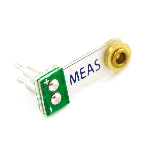
The model type of vibration sensor is the  Minisense 100 which is a low-cost cantilever-type vibration sensor loaded by a mass to offer high sensitivity at low frequencies. The pins are designed for easy installation and are solderable. Horizontal and vertical mounting options are offered as well as a reduced height version. The active sensor area is shield for improved RFI/ EMI rejection. The sensor has excellent linearity and dynamic range and may be used for detecting either continuous vibration or impacts. The mass may be modified to obtain alternative frequency response and sensitivity selection. 

Piezo Vibration Sensor - Small Horizontal
Minisense 100 Vibration Sensor

The application of vibration sensors are:

a) Washing Machine Load Imbalance
b) Vehicle Motion Sensor
c) Anti-Theft Devices
d) Vital Signs Monitoring
e) Tamper Detection
f) Impact Sensing

Piezo Vibration Sensor Testing

Conclusion:
This week I am going to learned about the vibration sensor as it is the one of the component which is used in my project. The type of vibration sensor and the application of of it need to take note so that it is suitable to use in this project. This project will used the Minisense 100 which is a piezoelectric vibration sensor. The vibration sensor sense when the rider had a crashed. The helmet will hits the ground and the vibration sensor detects the vibrations that are created when the helmet hits the ground and then the microcontroller will send a SMS containing information about the accident and location of accident. This will help the rider to get a help in a very short time. Hence, lives can be save.


Friday, 13 November 2015

FINAL YEAR PROJECT 1 (WEEK 9): Pressure Sensor

Objectives:
1) To know the operation theory for pressure sensor
2) To know the suitable pressure sensor

Method:
1) By making research in the internet

Pressure sensors are based on the principle of bending a membrane caused by the pressure in a liquid or gas. Pressure is an expression of the force required to stop a fluid from expanding and is usually stated in terms of force per unit area. A pressure sensor acts as a transducer. it generates a signal asa function of the pressure imposed.  On the membrane is a very thin conductive screened layer that follows the bending of the membrane. This bending can be measured in two different ways:

a) Can measure the distance between the conductive and resistive layer on the membrane and a reference layer in the housing of the sensor. The two layers form a capacity and the change in the distance show a change in the capacitive value can be measured.

b) The resistance of the conductive layers is changed when the membrane is bended. A smart mechanical layout of four resistive structures can form a stable Wheatstone bridge, comparable with the classical strain gauge sensors.

Both ways of measuring the pressure are widely used. Pressure sensors are used for control and monitoring in thousands of everyday applications. Pressure sensors can also be used to indirectly measure other variables such as fluid/gas flow, speed, water level, and altitude. It is alternatively can be called:

a) Pressure transducers
b) Pressure transmitters
c) Pressure senders
d) Pressure indicators
e) Piezometers
f) Manometers

There are many types of pressure sensors and the type of pressure sensor is listed below:

a) Gauge pressure sensor
    The difference of the medium and the atmospheric pressure is measured. Therefore, one side of the     membrane is always atmospheric pressure. A tire pressure gauge is an example of gauge pressure       measurement. When it indicates zero, then the pressure it is measuring is the same as the ambient       pressure.

b) Absolute pressure sensor
    This sensor measures the pressure relative to perfect vacuum. So one side of the membrane is             vacuum.

c) Differential pressure sensor
    Referenced to another pressure and can measure the difference between the two pressures. So both     sides can be anything. Differential pressure sensors are used to measure many properties such as         pressure drops across oil filters or air filters, fluid levels or flow rates. Most pressure sensors are         really differential sensors in technical way.

d) Sealed pressure sensor
    This sensor is similar to a gauge pressure sensor except that it measures pressure relative to some       fixed pressure rather than the ambient atmospheric pressure which varies according to the location      and the weather.

Pressure is sensed by mechanical elements such as plates, shells, and tubes that are designed and constructed to deflect when pressure is applied. This is the basic mechanism converting pressure to physical movement. Next, this movement must be transduced to obtain an electrical or other output. Finally, signal conditioning may be needed depending on the type of sensor and the application. The main types of sensing elements are Bourdon tubes, diaphragms, capsules, and bellows. 

figure
The basic pressure sensing elements can be configured as a C-shaped Bourdon tube (A); a helical Bourdon tube (B); flat diaphragm (C); a convoluted (D); a capsule (E); or a set of bellows (F).
There are many types of pressure-sensing technology. These are be divided by two basic categories of analog pressure sensors:

a) Force collector types
    These types of electronic pressure sensors generally use a force collector such a diaphragm, piston,     Bourdon tube or bellows to measure strain or deflection due to applied force(pressure) over an             area.

P= Force (F) / Area (A)
  • Piezoresistive strain gauge
  • Capacitive
  • Electromagnetic
  • Piezoelectric
  • Optical
  • Potentiometric
b) Other types of pressure sensor which use other properties such as density to infer pressure of a gas      or liquid.
  • Resonant
  • Thermal
  • Ionization
Manufacturers of pressure sensors have elaborate calibration facilities to verify the accuracy of their production test equipment. These are the equipment to do the calibration of pressure sensor:

a) Dead-Weight Tester
    A dead-weight tester uses calibrated weights that exert force on a piston which then acts on a fluid     to produce a test pressure. For high pressures (>500 psi), oil is typically used. For lower pressures,     pneumatic air bearing testers are available and are much more convenient as well as less messy to       use.
figure
Dead-weight testers is used to calibrate pressure sensors incorporate calibrated weights that exert force on a piston which in turn acts on a fluid to produce a test pressure. Oil-type testers commonly used for high pressures while pneumatic air bearing devices is used for lower pressures.
b) Manometer
    A mercury manometer is a simple pressure standard and may be used for gauge, differential, and         absolute measurements with a suitable reference. It is useful mainly for lower pressure work               because the height of the column of mercury will otherwise become unwieldy. 
figure
Mercury manometer to calibrate pressure sensors which can be used on gauge, differential, and absolute sensors with a suitable reference. It is used mainly to calibrate sensors designed to measure in the lower pressure ranges.
c) Low-cost Calibration
    Many of the higher performance commercially available pressure sensors are furnished with               individual text data. A sensor with excellent repeatability and hysteresis makes an excellent low-         cost in-house pressure calibration reference when combined with a pneumatic pressure regulator         and a source of air pressure.
figure
A sensor with excellent repeatability and hysteresis can be combined with a pneumatic pressure regulator and a source of a air pressure to yield an inexpensive in-house pressure calibration reference.

The factors to consider when selecting the pressure sensors are:

a) The medium for compatibility with the materials used in the sensor, the type such as gauge,                 absolute, or differential of measurement, the range, the type of electrical output, and the accuracy       required. 
b) Manufacturer's specifications apply to a particular temperature range. If the range of operation in a    given application is smaller, for example, the errors should ratio down. Total error can be computed    by adding the individual errors or by computing the geometric sum or root sum of the squares. 

The application of pressure sensors are:

a) Industrial
b) Automotive
c) Medical
d) Heating, Ventilating, Air Conditioning
e) Gas Boilers, Gas Ovens, Pellet Stoves

Conclusion:
This week I am going to learned about the pressure sensor as it is one of the component which used in my project. The type of pressure sensor and the application of each type need to take note so that it is suitable to use in the project. For my project, I will used the differential pressure sensor as it measure the differences between two pressures. By using this sensor, it can provide safety for the riders. The pressure sensor is connected to ADC so that the measurement can be read when both of it interface with microcontroller. This can be used to check whether the riders wear the helmet or not before they turn on their motorcycle. If they do not wear the helmet, the motorcycle will not start. 


Friday, 6 November 2015

FINAL YEAR PROJECT 1 (WEEK 8): Temperature Sensor

Objectives:
1) To know the operation theory of temperature sensor
2) To find the suitable temperature sensor

Method:
1) By making research in the internet

A temperature sensor basically senses temperature but it does it in a number of ways. A contact temperature sensor will read the temperature of an object that it is attached to physically. A non-contact temperature sensor can detect the temperature of an object that it is not attached to. This means that it can measure temperature of an object that is far away and does not have to touch the object at all. Whether in process industry applications or in laboratory settings, accurate temperature measurements are a critical part of success. Accurate temperature measurements are needed in medical applications, materials research in labs, electrical/electronic component studies, biology research, geological studies and electrical product device thermal characterization. To get the accurate temperature measurements, several consideration when selecting a temperature sensor is needed. These are the consideration that we need to know when selected the temperature sensor:

a) The type of application for the temperature sensor to used. For instance, ask ourselves with this following questions:

  • What is the device to be measured?
  • Is it ambient air temperature in a room or enclosure?
  • Is the electronic component with plastic or metal packaging that may or may not have high voltages present?
Some of these considerations can drive the choice of sensor due to environmental and safety factors, cost budget per sensor, and distance from sensor to instrument.


b) The range of expected measured temperature. For instance, an automobile engine block, when fully warmed up, can generate temperatures of greater than 100C. Most thermocouples can handle this temperature range and the type K is the most general purpose thermocouple for such applications. A type N would be good for the higher temperature because of their stability and resistance to high temperature oxidation. 

c) The available area of the sensor to be mounted to adequately sense the temperature to be measured. The device to be measured must have room enough to handle the selected sensor mounting. For example, an integrated circuit, (IC) is a tiny electronic component so the right sensor would depend on what parameter is to be measured, the IC package, or the lead frame or chip device itself. Most sensors come in variety of shapes and sizes and one is sure to fit the application. For the tiny electronic circuit of an IC, an electrically isolated resistance temperature detector (RTD) would probably be the best because of the size, isolation and accuracy of the RTD.

Temperature sensing can be done either through direct contact with the heating source or remotely which means without direct contact with the source using radiated energy instead. There are a wide variety of temperature sensors on the market today including thermocouples, RTD, thermistors, infrared and semiconductor sensors. These are the common five types of temperature sensors:

a) Thermocouple
A type of temperature sensor which is made by joining two dissimilar metals at one end. The joined end is referred to as the HOT JUNCTION. The other end of these dissimilar metals is referred as the COLD END or COLD JUNCTION. The cold junction is formed at the last point of thermocouple material. If there is a difference in temperature between the hot junction and cold junction, a small voltage is created. This voltage is referred to as an EME (electro-motive force) and can be measured and in turn used to indicate temperature.

Thermocouple

b) Resistance Temperature Detector (RTD)
A temperature sensing device whose resistance changes with temperature. Typically built from platinum, though devices made from nickel or copper are not uncommon, RTDs can take many different shapes like wire wound, thin film. To measure the resistance across an RTD, apply a constant current, measure the resulting voltage, and determine the RTD resistance. RTDs exhibit fairly linear resistance to temperature curves over their operating regions and any non-linearity are highly predictable and repeatable. The PT100 RTD evaluation board uses surface mount RTD to measure temperature. An external 2, 3, or 4-wire PT100 can also be associated with measure temperature in remote areas. The RTDs are biased using a constant current source. So as to reduce self-heat due to power dissipation, the current magnitude is moderately low. 

c) Thermistors
A temperature sensing device whose resistance changes with temperature. Thermistors, however, are made from semiconductor materials. Resistance is determined in the same manner as the RTD but thermistors exhibit a highly non-linear resistance versus temperature curve. Thus, in thermistors operating range we can see large resistance change for a very small temperature change. This makes for a highly sensitive device, ideal for set-point applications.

d) Semiconductor sensors
Classified into different types like Voltage Output, Current Output, Digital Output, Resistance output silicon and Diode temperature sensors. Modern semiconductor temperature sensors offer high accuracy and high linearity over an operating range of about 55C to +150C. Internal amplifiers can scale the output to convenient values like 10mV/C. They are also useful in cold-junction compensation circuits for wide temperature range thermocouples. This type of temperature sensor is a sensor ICs. There are variety of temperature sensor ICs that are available to simplify the broadest possible range of temperature monitoring challenges. These silicon temperature sensors differ significantly from the above mentioned types in a couple of important ways. The first is operating temperature range.  A temperature sensor IC can operate over the nominal IC temperature range of -55C to +150C. The second major difference is functionality.

As a silicon temperature sensor is an integrated circuit, it includes extensive signal processing circuitry within the same package as the sensor. There is no need to add compensation circuits for temperature sensor ICs. Some of these are analog circuits with either voltage or current output. The other one is the combining analog-sensing circuits with voltage comparators to provide alert functions. Some of it the analog-sensing circuitry with digital input/output and control register are combined together, making them an ideal solution for microprocessor-based systems.

Digital output sensor usually contains a temperature sensor, analog-to-digital converter (ADC), a two wire digital interface and registers controlling the IC's operation. Temperature is continuously measured and can be read at any time. If desired, the host processor can instruct the sensor to monitor temperature and take an output pin high or low if temperature exceeds a programmed limit. Lower threshold temperature can also be programmed and the host can be notified when temperature has dropped below this threshold. Therefore, digital output sensor can be used for reliable temperature monitoring in micro-processor based systems. 

Temperature Sensor
Temperature Sensor

The temperature sensor above has three terminals and the required maximum voltage is 5.5V supply. This type of sensor consists of a material that performs the operation according to temperature to vary the resistance. This change of resistance is sensed by circuit and it calculates temperature. When the voltage increases then the temperature also rises. It can be seen when it operates by using a diode. Temperature sensors directly connected to microprocessor input and thus capable of direct and reliable communication with microprocessors. The sensor unit can communicate effectively with low-cost processors without the need of A/D converters. An example for this temperature sensor is LM35. The LM35 series are precision integrated-circuit temperature sensors, whose output voltage is linearly proportional to the Celcius temperature. The LM35 is operates at -55C to 120C. 

e) Digital Temperature Sensors
It eliminate the necessity for extra components such as an A/D converter within the application and there is no need to calibrate components or the system at specific reference temperatures as needed when utilizing thermistors. Digital temperature sensors deal with everything, empowering the basic system temperature monitoring function to be simplified. One of the good thing for this type temeprature sensor is its precision output in degree Celcius. The sensor output is a balanced digital reading. This intends no other components such as an analog to digital converter and much simpler to use than a simple thermistor which provides a non-linear resistance with temperature variation. 

Type of sensors with applications

Conclusion:
This week I am going to learned about the temperature sensor as it is one of the component which used in my project. The type of temperature sensor and the application of each type need to take note so that it is suitable to use in the project. For my project, I will used the semiconductor sensors that is LM35 because it is based on voltage output. It is typically 3-pin devices which are power, ground and output. Besides that, this temperature sensor is easily connected to ADC so that the measurement can be read when both of it interface with microcontroller. This can be used to measure the temperature inside the helmet whether it is hot or not so that it can help the paramedics to check on the motorcyclist that had an accident.