Tuesday, 8 December 2015

FINAL YEAR PROJECT 1 (WEEK 13): Presentation Day and Proposal Report

Objective:
1) Preparation of Presentation Day
2) Preparation of Proposal Report

Method:
1) By making research in the internet

This week I will show about my proposal presentation and proposal report that will need to be assessed. 


The motorcycle do not start if the rider violated the rules when wearing the helmet


The work plan for Final Year Project 1 

The work plan for Final Year Project 2

References for research articles


The work plan is put in the proposal so that I can plan my work for this semester and the next semester. The improvise section shows that I need to do more researches about my project so that I can analyzed the outcome of this project.  I hope I can manage to design this project. 

Friday, 4 December 2015

FINAL YEAR PROJECT 1 (WEEK 12): LCD Display

Objectives:
1) To study about LCD display
2) To know the application of LCD display

Method:
1) By making research in the internet

A liquid-crystal display (LCD) is a flat panel display, electronic visual display, or video display that uses the light modulating properties of liquid crystals. Liquid crystals do not emit light directly. LCDs are available to display arbitrary images or fixed images with low information content which can be displayed or hidden such as preset words, digits and 7-segment displays as in a digital clock. they use the same basic technology except that arbitrary images are mafe up of a larger number of small pixels while other displays have larger elements.

There are important factors to consider when evaluating an LCD:


  • Resolution vs. Range: Fundamentally resolution is the granularity with which a performance feature of the display divided. Resolution is often confused with range or the total end-to-end output of the display. Each of the major features of a display has both a resolution and a range that are tied to each other but very different. Frequently the range is an inherent limitation of the display while the resolution is a function of the electronics that make the display work.
  • Spatial performance: LCDs come in only one size for a variety of applications and a variety of resolutions within each of those applications. LCD spatial performance is also sometimes described in terms of the diagonal distance from one corner to its opposite. The spatial resolution of an LCD is expressed by the number of columns and rows of pixels. 
  • Temporal/timing performance: As compared to spatial performance, temporal performance is a feature where smaller is better. The range is the pixel response time of an LCD or how quickly a sub-pixel's brightness changes from one level to another. REfresh rate or the temporal resolution of an LCD is the number of times per second in which the display draws the data is being given. Since activated LCD pixels do not flash on/off between frames. 
  • Color performance: Color performance include color gamut which is the range of colors that can be displayed and color depth which is the color resolution or the resolution or fineness with which the color range is divided. 
LCD display applications:

  • Computer monitors
  • Televisions
  • Instrument panels
  • Aircraft cockpit displays
  • Signage
  • DVD players
  • Clocks
  • Watches
  • Calculators
  • Telephones
  • Gaming devices
For this project, the LCD display that will used is 16x2 LCD display. This LCD display is much more informative output device than a single LED. The LCD is a display that can easily show characters on its screen. They have a couple of lines to large displays. Some LCDs are specifically designed for specific applications to display graphic images. These modules are replacing 7-segments and other multi-segment LEDs. LCD can be easily interfaced with microcontroller to display a message or status of the device. It can be operated in two modes: 4-bit mode and 8-bit mode. This LCD has two registers namely command register and data register. It is having three selection lines and 8 data lines. By connecting the three selection lines and data lines with the microcontroller, the messages can be displayed on LCD.
LCD display

LCD instructions set for controlling the LCD display using microcontrollers
PIN description
Interfacing 16x2 LCD display with 8051 microcontroller
In the above figure, 3 selected lines EN, R/W, RS will be used for controlling the LCD display. EN pin will be used for enabling the LCD display for communicating with microcontroller, RS with be used for register selection. When RS is set microcontroller will send instructions as data when RS is clear microcontroller will send the instructions as commands. For writing data RW should be 0 and for reading RW should be 1.

Conclusion:


This week I am going to learned about the LCD display as it is the one of the component which is used in my project. The type of LCD display and the application of of it need to take note so that it is suitable to use in this project. This project will used the 16x2 LCD display. The LCD display is used to display the location of the accident, the information whether the rider is drunken or not and display the motorcycle will start or not if the rider does not violated the rules when he or she wearing the helmet.  This will help the rider to get a help in a very short time. Hence, lives can be save.

Friday, 27 November 2015

FINAL YEAR PROJECT 1 (WEEK 11): Alcohol Sensor

Objectives:
1) To know the operation theory of alcohol sensor
2) To find suitable alcohol sensor

Method:
1) By making research in the internet

There are a number of alcohol sensors on the market. Police use them to estimate blood alcohol concentration (BAC) although this is more accurately determined through a blood test. Alcohol gas sensor detects the concentration of alcohol gas in the air and output its reading as an analog voltage. On the market there are different types of sensors to detect gas alcohol such as ethanol. There are five common families to detect the alcohol which are:

1) Catalytic combustion sensors
2) Sensors semiconductor flat surfaced (advanced flat surfaced alcohol sensor)
3) Sensors semiconductor specific
4) Electrochemical sensors(fuel sensor)
5) Infrared sensors

For this project, semiconductor sensor is chosen to detect the alcohol gas and the type that had be chosen is MQ-3 semiconductor sensor. Sensitive material of MQ-3 gas sensor is thin oxide (SnO2)
which with lower conductivity in clean air. When the target alcohol gas exist, the sensor's conductivity is more higher along with the gas concentration rising. The change of conductivity is converted to correspond output signal of gas concentration. MQ-3 gas sensor has high sensitivity to alcohol and has good resistance to disturb of gasoline, smoke and vapor. The sensor could be used to detect alcohol with different combustion, it is with low cost and suitable for different application.

Configuration 


Features
  • Good sensitivity to alcohol gas
  • Long life and low cost
  • Simple drive circuit

Application

  • Vehicle alcohol detector
  • Portable alcohol detector
The alcohol sensor MQ-3 suitable for detecting alcohol concentration in breath like a common breathalyzer such as portable alcohol detection. It provides an analog resistive output based on alcohol concentration. The resistance of the sensor reduces when alcohol concentration increases. The sensor gives output as per the condition of the breath through the logic circuit which is sent to microporcessor. This power supply needs for this sensor is 5V. 

MQ-3 ALCOHOL SENSOR CIRCUIT

PIN CONNECTION
MQ-3 ALCOHOL SENSOR

There are conditions that we need to follow so that the this alcohol function as we need. The conditions are:

  1. Organic silicon steam cause invalid, sensors must be avoid exposing to silicon bond, silicon latex, putty or plastic contain silicon environment.
  2. If the sensors exposed to high concentration corrosive gas, it will not only result in corrosion of sensors structure but also it cause sincere sensitivity attenuation.
  3. The sensor performance will be change badly if sensors be sprayed polluted by alkali metals salt especially brine or be exposed to halogen such as fluorin.
  4. Sensitivity of the sensors will be reduced when spattered or dipped in water.
  5. Do avoid icing on sensor's surface otherwise sensor will lose sensitivity.
  6. Applied voltage on sensor should not be higher than stipulated value otherwise it cause down-line or heater damaged and bring on sensors' sensitivity characteristic change badly.
  7. In indoor conditions, slightly water condensation will effect sensors performance lightly. however, if water condensation on sensors surface and keep a certaion period, sensor sensitivity will be decreased.
  8. The sensor resistance produce reversible drift if it's stored for long time without eectrify which drift related with storage conditions. sensors should be stored in airproof without silicon gel bag with clean air. for the sensors with long time storage but no electrify, they eed long aging time for stability before using.
  9. Continual vibration will result in sensors down-lead response then repture. 
  10. If sensors meet strong concussion, it may lead its lead wire disconnected. 
First test with MQ-3 Alcohol sensor

Conclusion:
This week I am going to learned about the alcohol sensor as it is the one of the component which is used in my project. The type of alcohol sensor and the application of of it need to take note so that it is suitable to use in this project. This project will used the MQ-3 alcohol sensor. The alcohol sensor sense the alcoholic content if the rider is drunken. If the driver is drunken, the LCD display will displayed to give information that the rider is drunken and the motorcycle cannot start. This will ensure safety of the rider because he or she cannot ride the motorcycle if he or she is drunken which will decrease the potential of the accident happens.


Friday, 20 November 2015

FINAL YEAR PROJECT 1 (WEEK 10): Vibration Sensor

Objectives:
1) To know the operation theory of vibration sensor
2) To find the suitable vibration sensor

Method:
1) By making research in the internet

Sometimes chaos begins with a low rumble or a small shake. If a sensor is involved, it might be measuring the first vibrational movements of an earthquake or a mechanical failure in an industrial setting. It's typically noise that gives use the first clue that trouble looms. There can be two aspects of vibration that we need to pay close attention if we want to avoid the trouble. The aspects are:

a) The monitoring of vibration
b) Maintenance based on sensor data to avoid future issues

As machines or the electronics and components machines begin to move back and forth, the vibration is preventing a smooth flow of energy. The flow is interrupted, hence the noise and the shake. It may be overload due to some sort of stress or the components themselves may have reached their useful life such as gears, teeth, bearing, or belts may be in process of failure.

Vibration is needed to monitor because in industrial machinery, the vibration produced are vital indicators of machinery health. by monitoring the vibration levels over time, it allows prediction of problems before serious damage can occur. Despite the advances made in vibration monitoring and analysis equipment, the selection of sensors and the way they are mounted on a machine remain critical factors in determining the success of any monitoring program. The key to proper machine monitoring however is the proper choice of sensor for the particular installation. The best instrumentation and software available will not provide the definitive information without using the proper sensor regarding the mechanical operating condition or deficiencies of the machine. The ability to monitor more than one machine parameter with the same sensor can give added insight to machine performance at a more economical cost. To select the vibration sensors, there are three parameters representing motion detected by vibration monitors. There are:

a) Displacement
b) Velocity
c) Acceleration

These parameters can be measured by a variety of motion sensors and are mathematically related. For instance, displacement is the first derivative of velocity and velocity is the first derivative for acceleration. The selection of a sensor is proportional to displacement, velocity or acceleration which depends on the frequencies of interest and the signal levels involved. Sensor selection and installation is often the most critical determining factor in accurate diagnoses of machinery condition. 

The relationship of  displacement and velocity and acceleration

The vibration sensor that will applied for this project is piezoelectric sensors. The piezoelectric property is a reversible phenomenon. Whenever an electric excitation voltage is applied across the opposite faces of quartz crystal, it starts to vibrate and hence produces mechanical oscillations. Whenever mechanical vibrations are applied to the crystal, it produces electric potential across of oscillations depends on the physical size and the shape of the crystal. The smaller dimensions of crystals produce higher frequencies and bigger crystals produce lower frequencies. 

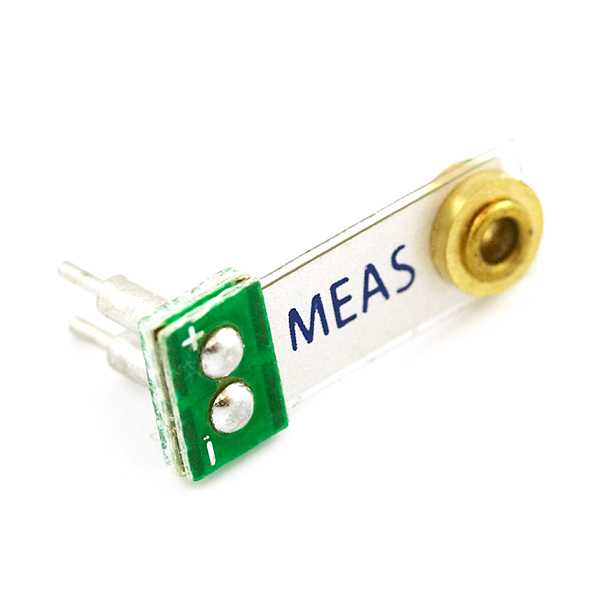
The model type of vibration sensor is the  Minisense 100 which is a low-cost cantilever-type vibration sensor loaded by a mass to offer high sensitivity at low frequencies. The pins are designed for easy installation and are solderable. Horizontal and vertical mounting options are offered as well as a reduced height version. The active sensor area is shield for improved RFI/ EMI rejection. The sensor has excellent linearity and dynamic range and may be used for detecting either continuous vibration or impacts. The mass may be modified to obtain alternative frequency response and sensitivity selection. 

Piezo Vibration Sensor - Small Horizontal
Minisense 100 Vibration Sensor

The application of vibration sensors are:

a) Washing Machine Load Imbalance
b) Vehicle Motion Sensor
c) Anti-Theft Devices
d) Vital Signs Monitoring
e) Tamper Detection
f) Impact Sensing

Piezo Vibration Sensor Testing

Conclusion:
This week I am going to learned about the vibration sensor as it is the one of the component which is used in my project. The type of vibration sensor and the application of of it need to take note so that it is suitable to use in this project. This project will used the Minisense 100 which is a piezoelectric vibration sensor. The vibration sensor sense when the rider had a crashed. The helmet will hits the ground and the vibration sensor detects the vibrations that are created when the helmet hits the ground and then the microcontroller will send a SMS containing information about the accident and location of accident. This will help the rider to get a help in a very short time. Hence, lives can be save.


Friday, 13 November 2015

FINAL YEAR PROJECT 1 (WEEK 9): Pressure Sensor

Objectives:
1) To know the operation theory for pressure sensor
2) To know the suitable pressure sensor

Method:
1) By making research in the internet

Pressure sensors are based on the principle of bending a membrane caused by the pressure in a liquid or gas. Pressure is an expression of the force required to stop a fluid from expanding and is usually stated in terms of force per unit area. A pressure sensor acts as a transducer. it generates a signal asa function of the pressure imposed.  On the membrane is a very thin conductive screened layer that follows the bending of the membrane. This bending can be measured in two different ways:

a) Can measure the distance between the conductive and resistive layer on the membrane and a reference layer in the housing of the sensor. The two layers form a capacity and the change in the distance show a change in the capacitive value can be measured.

b) The resistance of the conductive layers is changed when the membrane is bended. A smart mechanical layout of four resistive structures can form a stable Wheatstone bridge, comparable with the classical strain gauge sensors.

Both ways of measuring the pressure are widely used. Pressure sensors are used for control and monitoring in thousands of everyday applications. Pressure sensors can also be used to indirectly measure other variables such as fluid/gas flow, speed, water level, and altitude. It is alternatively can be called:

a) Pressure transducers
b) Pressure transmitters
c) Pressure senders
d) Pressure indicators
e) Piezometers
f) Manometers

There are many types of pressure sensors and the type of pressure sensor is listed below:

a) Gauge pressure sensor
    The difference of the medium and the atmospheric pressure is measured. Therefore, one side of the     membrane is always atmospheric pressure. A tire pressure gauge is an example of gauge pressure       measurement. When it indicates zero, then the pressure it is measuring is the same as the ambient       pressure.

b) Absolute pressure sensor
    This sensor measures the pressure relative to perfect vacuum. So one side of the membrane is             vacuum.

c) Differential pressure sensor
    Referenced to another pressure and can measure the difference between the two pressures. So both     sides can be anything. Differential pressure sensors are used to measure many properties such as         pressure drops across oil filters or air filters, fluid levels or flow rates. Most pressure sensors are         really differential sensors in technical way.

d) Sealed pressure sensor
    This sensor is similar to a gauge pressure sensor except that it measures pressure relative to some       fixed pressure rather than the ambient atmospheric pressure which varies according to the location      and the weather.

Pressure is sensed by mechanical elements such as plates, shells, and tubes that are designed and constructed to deflect when pressure is applied. This is the basic mechanism converting pressure to physical movement. Next, this movement must be transduced to obtain an electrical or other output. Finally, signal conditioning may be needed depending on the type of sensor and the application. The main types of sensing elements are Bourdon tubes, diaphragms, capsules, and bellows. 

figure
The basic pressure sensing elements can be configured as a C-shaped Bourdon tube (A); a helical Bourdon tube (B); flat diaphragm (C); a convoluted (D); a capsule (E); or a set of bellows (F).
There are many types of pressure-sensing technology. These are be divided by two basic categories of analog pressure sensors:

a) Force collector types
    These types of electronic pressure sensors generally use a force collector such a diaphragm, piston,     Bourdon tube or bellows to measure strain or deflection due to applied force(pressure) over an             area.

P= Force (F) / Area (A)
  • Piezoresistive strain gauge
  • Capacitive
  • Electromagnetic
  • Piezoelectric
  • Optical
  • Potentiometric
b) Other types of pressure sensor which use other properties such as density to infer pressure of a gas      or liquid.
  • Resonant
  • Thermal
  • Ionization
Manufacturers of pressure sensors have elaborate calibration facilities to verify the accuracy of their production test equipment. These are the equipment to do the calibration of pressure sensor:

a) Dead-Weight Tester
    A dead-weight tester uses calibrated weights that exert force on a piston which then acts on a fluid     to produce a test pressure. For high pressures (>500 psi), oil is typically used. For lower pressures,     pneumatic air bearing testers are available and are much more convenient as well as less messy to       use.
figure
Dead-weight testers is used to calibrate pressure sensors incorporate calibrated weights that exert force on a piston which in turn acts on a fluid to produce a test pressure. Oil-type testers commonly used for high pressures while pneumatic air bearing devices is used for lower pressures.
b) Manometer
    A mercury manometer is a simple pressure standard and may be used for gauge, differential, and         absolute measurements with a suitable reference. It is useful mainly for lower pressure work               because the height of the column of mercury will otherwise become unwieldy. 
figure
Mercury manometer to calibrate pressure sensors which can be used on gauge, differential, and absolute sensors with a suitable reference. It is used mainly to calibrate sensors designed to measure in the lower pressure ranges.
c) Low-cost Calibration
    Many of the higher performance commercially available pressure sensors are furnished with               individual text data. A sensor with excellent repeatability and hysteresis makes an excellent low-         cost in-house pressure calibration reference when combined with a pneumatic pressure regulator         and a source of air pressure.
figure
A sensor with excellent repeatability and hysteresis can be combined with a pneumatic pressure regulator and a source of a air pressure to yield an inexpensive in-house pressure calibration reference.

The factors to consider when selecting the pressure sensors are:

a) The medium for compatibility with the materials used in the sensor, the type such as gauge,                 absolute, or differential of measurement, the range, the type of electrical output, and the accuracy       required. 
b) Manufacturer's specifications apply to a particular temperature range. If the range of operation in a    given application is smaller, for example, the errors should ratio down. Total error can be computed    by adding the individual errors or by computing the geometric sum or root sum of the squares. 

The application of pressure sensors are:

a) Industrial
b) Automotive
c) Medical
d) Heating, Ventilating, Air Conditioning
e) Gas Boilers, Gas Ovens, Pellet Stoves

Conclusion:
This week I am going to learned about the pressure sensor as it is one of the component which used in my project. The type of pressure sensor and the application of each type need to take note so that it is suitable to use in the project. For my project, I will used the differential pressure sensor as it measure the differences between two pressures. By using this sensor, it can provide safety for the riders. The pressure sensor is connected to ADC so that the measurement can be read when both of it interface with microcontroller. This can be used to check whether the riders wear the helmet or not before they turn on their motorcycle. If they do not wear the helmet, the motorcycle will not start. 


Friday, 6 November 2015

FINAL YEAR PROJECT 1 (WEEK 8): Temperature Sensor

Objectives:
1) To know the operation theory of temperature sensor
2) To find the suitable temperature sensor

Method:
1) By making research in the internet

A temperature sensor basically senses temperature but it does it in a number of ways. A contact temperature sensor will read the temperature of an object that it is attached to physically. A non-contact temperature sensor can detect the temperature of an object that it is not attached to. This means that it can measure temperature of an object that is far away and does not have to touch the object at all. Whether in process industry applications or in laboratory settings, accurate temperature measurements are a critical part of success. Accurate temperature measurements are needed in medical applications, materials research in labs, electrical/electronic component studies, biology research, geological studies and electrical product device thermal characterization. To get the accurate temperature measurements, several consideration when selecting a temperature sensor is needed. These are the consideration that we need to know when selected the temperature sensor:

a) The type of application for the temperature sensor to used. For instance, ask ourselves with this following questions:

  • What is the device to be measured?
  • Is it ambient air temperature in a room or enclosure?
  • Is the electronic component with plastic or metal packaging that may or may not have high voltages present?
Some of these considerations can drive the choice of sensor due to environmental and safety factors, cost budget per sensor, and distance from sensor to instrument.


b) The range of expected measured temperature. For instance, an automobile engine block, when fully warmed up, can generate temperatures of greater than 100C. Most thermocouples can handle this temperature range and the type K is the most general purpose thermocouple for such applications. A type N would be good for the higher temperature because of their stability and resistance to high temperature oxidation. 

c) The available area of the sensor to be mounted to adequately sense the temperature to be measured. The device to be measured must have room enough to handle the selected sensor mounting. For example, an integrated circuit, (IC) is a tiny electronic component so the right sensor would depend on what parameter is to be measured, the IC package, or the lead frame or chip device itself. Most sensors come in variety of shapes and sizes and one is sure to fit the application. For the tiny electronic circuit of an IC, an electrically isolated resistance temperature detector (RTD) would probably be the best because of the size, isolation and accuracy of the RTD.

Temperature sensing can be done either through direct contact with the heating source or remotely which means without direct contact with the source using radiated energy instead. There are a wide variety of temperature sensors on the market today including thermocouples, RTD, thermistors, infrared and semiconductor sensors. These are the common five types of temperature sensors:

a) Thermocouple
A type of temperature sensor which is made by joining two dissimilar metals at one end. The joined end is referred to as the HOT JUNCTION. The other end of these dissimilar metals is referred as the COLD END or COLD JUNCTION. The cold junction is formed at the last point of thermocouple material. If there is a difference in temperature between the hot junction and cold junction, a small voltage is created. This voltage is referred to as an EME (electro-motive force) and can be measured and in turn used to indicate temperature.

Thermocouple

b) Resistance Temperature Detector (RTD)
A temperature sensing device whose resistance changes with temperature. Typically built from platinum, though devices made from nickel or copper are not uncommon, RTDs can take many different shapes like wire wound, thin film. To measure the resistance across an RTD, apply a constant current, measure the resulting voltage, and determine the RTD resistance. RTDs exhibit fairly linear resistance to temperature curves over their operating regions and any non-linearity are highly predictable and repeatable. The PT100 RTD evaluation board uses surface mount RTD to measure temperature. An external 2, 3, or 4-wire PT100 can also be associated with measure temperature in remote areas. The RTDs are biased using a constant current source. So as to reduce self-heat due to power dissipation, the current magnitude is moderately low. 

c) Thermistors
A temperature sensing device whose resistance changes with temperature. Thermistors, however, are made from semiconductor materials. Resistance is determined in the same manner as the RTD but thermistors exhibit a highly non-linear resistance versus temperature curve. Thus, in thermistors operating range we can see large resistance change for a very small temperature change. This makes for a highly sensitive device, ideal for set-point applications.

d) Semiconductor sensors
Classified into different types like Voltage Output, Current Output, Digital Output, Resistance output silicon and Diode temperature sensors. Modern semiconductor temperature sensors offer high accuracy and high linearity over an operating range of about 55C to +150C. Internal amplifiers can scale the output to convenient values like 10mV/C. They are also useful in cold-junction compensation circuits for wide temperature range thermocouples. This type of temperature sensor is a sensor ICs. There are variety of temperature sensor ICs that are available to simplify the broadest possible range of temperature monitoring challenges. These silicon temperature sensors differ significantly from the above mentioned types in a couple of important ways. The first is operating temperature range.  A temperature sensor IC can operate over the nominal IC temperature range of -55C to +150C. The second major difference is functionality.

As a silicon temperature sensor is an integrated circuit, it includes extensive signal processing circuitry within the same package as the sensor. There is no need to add compensation circuits for temperature sensor ICs. Some of these are analog circuits with either voltage or current output. The other one is the combining analog-sensing circuits with voltage comparators to provide alert functions. Some of it the analog-sensing circuitry with digital input/output and control register are combined together, making them an ideal solution for microprocessor-based systems.

Digital output sensor usually contains a temperature sensor, analog-to-digital converter (ADC), a two wire digital interface and registers controlling the IC's operation. Temperature is continuously measured and can be read at any time. If desired, the host processor can instruct the sensor to monitor temperature and take an output pin high or low if temperature exceeds a programmed limit. Lower threshold temperature can also be programmed and the host can be notified when temperature has dropped below this threshold. Therefore, digital output sensor can be used for reliable temperature monitoring in micro-processor based systems. 

Temperature Sensor
Temperature Sensor

The temperature sensor above has three terminals and the required maximum voltage is 5.5V supply. This type of sensor consists of a material that performs the operation according to temperature to vary the resistance. This change of resistance is sensed by circuit and it calculates temperature. When the voltage increases then the temperature also rises. It can be seen when it operates by using a diode. Temperature sensors directly connected to microprocessor input and thus capable of direct and reliable communication with microprocessors. The sensor unit can communicate effectively with low-cost processors without the need of A/D converters. An example for this temperature sensor is LM35. The LM35 series are precision integrated-circuit temperature sensors, whose output voltage is linearly proportional to the Celcius temperature. The LM35 is operates at -55C to 120C. 

e) Digital Temperature Sensors
It eliminate the necessity for extra components such as an A/D converter within the application and there is no need to calibrate components or the system at specific reference temperatures as needed when utilizing thermistors. Digital temperature sensors deal with everything, empowering the basic system temperature monitoring function to be simplified. One of the good thing for this type temeprature sensor is its precision output in degree Celcius. The sensor output is a balanced digital reading. This intends no other components such as an analog to digital converter and much simpler to use than a simple thermistor which provides a non-linear resistance with temperature variation. 

Type of sensors with applications

Conclusion:
This week I am going to learned about the temperature sensor as it is one of the component which used in my project. The type of temperature sensor and the application of each type need to take note so that it is suitable to use in the project. For my project, I will used the semiconductor sensors that is LM35 because it is based on voltage output. It is typically 3-pin devices which are power, ground and output. Besides that, this temperature sensor is easily connected to ADC so that the measurement can be read when both of it interface with microcontroller. This can be used to measure the temperature inside the helmet whether it is hot or not so that it can help the paramedics to check on the motorcyclist that had an accident. 


Friday, 23 October 2015

FINAL YEAR PROJECT 1 (WEEK 7): Sensors

Objective:
1) To know the definition of sensors
2) To know the type of sensors
3) To know the application of sensors

Methods:

1) By making research in the internet

Definition
A device that detects and responds to some type of input from the physical environment. A sensor is a type of transducer. Sensors may provide various types of output but typically use electrical or optical signals. The specific input could be light, heat, motion, moisture, pressure, or any one of a great number of other environmental phenomena. The output is generally a signal that is converted to human-readable display at the sensor location or transmitted electronically over a network for reading or further processing.

Criteria to choose a sensor
There are certain features which have to be considered when we choose a sensor. These are the following criteria:

a) High sensitivity: Sensitivity indicates how much the output of the device changes with unit change in input which means the quantity to be measured. For example the voltage of a temperature sensor changes by 1mV for every 1C change in temperature than the sensitivity of the sensor is said to be 1mV/C.
b) Environmental condition: It usually has limits for temperature or humidity.
c) Linearity: The output should change linearly with the input.
d) High resolution: The smallest change in the input that the device can detect.
e) Less noise and disturbance.
f) Less power consumption.
g) Range: The measurement limit of sensor
h) Calibration: It is essential for most of the measuring devices as the readings changes with time.
i) Cost
j) Repeatability: The reading that varies is repeatedly measured under the same environment.

Type and Application of sensors
Sensors are classified based on the nature of quantity they measure. These are the types of sensors with few examples:

a) Acoustic and Sound Sensor. Example: microphone, hydrophone
b) Temperature Sensor. For instance, in a mercury-based glass thermometer, the input is temperature. The liquid contained expands and contracts in response. It cause the level to be higher or lower on the marked gauge which is human-readable.
c) Oxygen Sensor. For instance, an oxygen sensor in a car's emission control system detects the gasoline or oxygen ratio. It is usually through a chemical reaction that generates a voltage. A computer in the engine reads the voltage and if the mixture is not optimal, the read just balance.
d) Photo Sensor. It detects the presence of visible light, infrared transmission (IR) and ultraviolet (UV) energy.
e)  Automotive Sensor. Example: Speedometer, radar gun
f) Chemical Sensor. Example: PH sensor which is a sensor that detect the presence of different gases or liquids.
g) Electric and Magnetic Sensor. Example: galvanometer, Hall sensor which is used to measure flux density, metal detector.
h) Environmental Sensor. Example: rain gauge, snow gauge, moisture sensor.
i) Optical Sensor. Example: photodiode, phototransistor, wave front sensor.
j) Mechanical Sensor. Example: strain gauge, potentiometer which is use to measure displacement.


different type sensors

Type and Application of sensors
Conclusion:
This week I am going to explain about sensors. There are many type of sensors nowadays and the sensor is some kind an input from the physical environment such as temperature, humidity, light intensity, blood pressure, speed and many more. After I had done this research about the sensors, so I can choose which type of sensor that is suitable for my project. The sensor that I had chose will connected to the ADC as the ADC can convert analog signal which is the physical quantity measurement into digital signal or the measurement from the analog signal can be read after the signal conversion is done. 

Friday, 16 October 2015

FINAL YEAR PROJECT 1 (WEEK 6): Selection of ADC chips

Objectives:

1) To know the factors to consider when selecting the ADC chips
2) To find the differences between ADC 0804 and ADC 0809

Method:
1) By making in the internet

Analog-to-digital converters are among the most widely used devices for data acquisition. Digital computers use binary values but in the physical world everything is analog which means continuous signal. the example of physical quantities are temperature, pressure, humidity and many more and basically it is the physical quantities that we deal every day. The physical quantity is converted to electrical signals by using a device which is known as a transducers or sensors. Sensors for temperature, humidity, pressure and many other natural quantities produce an output that is voltage or current. Thus, we need to translate the analog signals to digital numbersby using analog-digital converter so that the microcontroller can read and process them. An ADC has n-bit resolution and this is shown in table below:

Vcc = 5V


The higher-resolution ADC provides a smaller steps size, where step size is the smallest change that can be discerned by an ADC. For now, we just only examine 8-bit ADC chips. Other factors that we need to consider when selecting the chips is the conversion time. Conversion time is the time taken for ADC to convert the analog input to a digital or binary number. The ADC chips either parallel or serial. In parallel ADC, 8 or more pins dedicated to bringing out the binary data but in serial ADC , it used only one pin to bringing out the binary data. For this project, the analog input channel must more than the digital output channel as it is used two sensors to connect with the ADC.

Next, to choose the suitable ADC chips for a project, we need to compare the ADC chips. For my project, I need to choose whether ADC 0804 chips or ADC 0809 chips so that the input signal that I used can read by using the ADC.  The result by comparing the ADC 0804 and ADC 0809 are shown below:

No./Type
ADC 0804
ADC 0809
1)
Can only take single analog signal.
Can be used to take up to 8 different analog signals.
2)
Does not have selector input pins.
Because the ADC 0809 can take up to 8 different analog signals, a multiplexer scheme is used to select the 8 different analog channels. Thus, it has 3 selector input pins.
3)
The ADC 0804 control signals are WR*,INTR* and RD* signals which are read all active low signals.
The ADC 0809 control signals are called SC, ALE, EOC and OE which are active high signals except EOC.
4)
Have one reference voltage (Vref/2).
Have two reference voltage (Vref+ and Vref-).
5)
Use INTR pin for end of conversion.
Use EOC for end of conversion.
6)
Reading the data using RD pin.
Reading the data use OE pin.
7)
The speed of conversion cannot be faster than 110 per second.
The speed of conversion cannot be faster than 100 micro second.

Notes:
a) WR (Write)
b) INTR (Interrupt)
c) RD (Read)
d) SC (Start Conversion)
e) ALE (Address Latch Enable)
f) EOC (End of Conversion)
g) OE (Output Enable)

Conclusion:
This week I am going to tell about the differences of ADC chips and the factors that we need to consider when selecting the ADC chips as it is very important when we need to convert our analog input signal to digital signal so that we can read the signal. From this research, I learned that if we have many analog input signals, we need to use ADC 0809 as it has 8 input analog channel compared to ADC 0804. For this project, I used two sensors to connect with the ADC which are temperature sensor and pressure sensor. So, by using the right components, it can reduce the cost to implement the project rather than used try and error process to check whether the components is suitable or not for this project. 

Friday, 9 October 2015

FINAL YEAR PROJECT 1 (WEEK 5): Analog-to-Digital Converter (ADC)

Objectives:

1) To study about Analog-to-Digital Converter (ADC)
2) To understand the operation theory of Analog-to-Digital Converter (ADC)

Method:
1) By making research in the internet

An analog-to-digital converter (ADC) converts analog signals into digital signals without altering their essential content. The analog information is transmitted by modulating a continuous transmission. Besides that, it is also by amplifying the strength of the signal or varying its frequency in order to add or subtract data. The input to an analog-to-digital converter consists of a voltage which varies among a theoretically infinite number of values. The output of the ADC defined levels or states. The simplest digital signals only have two states and are called binary. Digital signals are transmitted in a more efficient way than analog signals because well-defined digital impulses are easier for an electronic circuit to distinguish than chaotic noise. The characteristic curve of an ideal 3-bit ADC. The analog input range usually is from 0 V to 5 V. The input signal can be divided by 8 (2^3=8) ranges, at each range all the analog values use the same binary code to represent and this binary code is corresponding with the mid-value. Therefore, during the processing converter, it consists of ± 1/2 least significant bit (LSB) quantization uncertainty or quantization error and also includes the previous converter that has analog error, then all of the errors comprise the error value of ADC. The number of bits of the converter need to increase so that it can reduce the quantization error. The more the number of bits, the more the number ofranges and the data signal will be more detail. This is because the ± 1/2 LSB becomes small. Thus, the quantization error will reduce. When the digital output changes LSB, the required input voltage value also changes and this is known as quantization value (Q). The methods of conversion for analog to digital converter are various, sampel and hold (S&H) circuit which is it will capture the inpus signal Vin to avoid normally can be divided as analog-to-digital (A/D) conversion methods. htere are digital-ramp ADC, successive approximation ADC, flash ADC and tracking ADC.

There are many types of ADC but there are three types of ADC that commonly used. There are:
1) Digital Ramp ADC
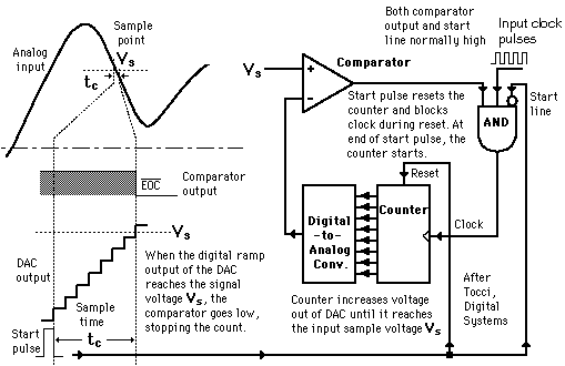
    The conversion from analog to digital form inherently involves comparator action whereby the value of the analog voltage at some point in time is compared with some standard. By applying the analog voltage to one terminal of a comparator and trigger a binary  which drives a digital-to-analog converter (DAC), the value of the analog voltage at some point can get. The output of the DAC is applied to the other terminal of the comparator. Since the output of the DAC is increasing with the counter, it triggered the comparator at some point when its voltage exceeds the analog input. The transition of the comparator stops the binary counter which is at that point holds the digital value corresponding to the analog voltage.

2) Successive Approximation ADC
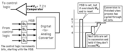
   This type of ADC is much faster than the digital ramp ADC because it uses digital logic to converge on the value closest to the input voltage. A comparator and a digital-to-analog converter (DAC) are used in the process. These is an illustration of 4-bit SAC with 1 volt step size.

3) Flash ADC
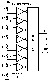
    A 3-bit flash ADC with resolution 1 volt is illustrated. The resistor net and comparators provide an input to the combinational logic circuit. Therefore, the conversion time is just the propagation delay through the network. Itis not limited by the clock rate or some convergence sequence. This type of ADC requires a comparator for each value of output although it is the fastest type of ADC. The ADCs are available in IC form up to 8-bit and 10-bit flash ADCs. A truth table has been executed from the encoder logic and then it is converted to the ladder of inputs to the binary number output.

Conclusion:
This week I am going to tell about the analog-to-digital converter (ADC) which is one of the important components to implement this project. This week I learned the type of ADC in industries and how this ADC will help me to do this project. 

Friday, 2 October 2015

FINAL YEAR PROJECT 1 (WEEK 4): Global Positioning System (GPS)

Objectives:

1) To study about Global Positioning System (GPS)
2) To know how GPS works

Methods:

1) By making research in the internet

Results:
How does GPS works
     Global Positioning System is a network of orbiting satellites that send precise details of their position in space back to earth. GPS is well-known for its military uses and was first developed by the US for the war. during early 1980s, the GPS is free to everyone with GPS receiver. Wherever you are on the planet, at least four GPS satellites are 'visible' at any time. Each one transmits information about its position and the current time at regular intervals. The signals is travelling at the speed of light intercepted by your GPS receiver which calculates how far away each satellite is based on how long it took for the messages to arrive. Your GPS receiver can pinpoint your location using a process called trilateration. It happens once it has information on how far away at least three satellites are. Imagine you are standing somewhere on Earth with three satellites in the sky above you. If you know how far away you are from the satellite A, then you will know that you must be located somewhere on the red circle. You can work out your location by seeing where the three circles intersect if you do the same for satellites B and C. Although it uses overlapping spheres rather than circles, it is just what your GPS receiver does. These satellites can be used to calculate a 2-D position which is latitude and longitude besides the track movement. The more satellites there are above the horizon, the more accurately your GPS unit can determine where you are. The receiver can determine the user's 3-D position which is latitude, longitude and altitude with four or more satellites in view. Once the user's position has been determined, the GPS unit can calculate other information such as speed, bearing, track, trip distance, distance to destination, sunrise and sunset time and many more. Nowadays, portable navigation device can give drivers their precise location to within a few meters and it is enough to navigate roadways. The 24 satellites that make up the GPS space segment are orbiting the earth about 12,000 miles above us. GPS is powered by solar energy but they also have backup batteries onboard to keep them running in the event of a solar eclipse when there is no solar power. Small rocket boosters on each satellite keep them flying in the correct path.
Three satellites that can give signals to GPS receiver 

Conclusion:
      This week I am going to tell about the Global Positioning System (GPS) which is one of the part that is very useful for this project as it is can located the place of the accident happens. This will save many lives as the ambulance and the family members who came to rescue the motorcyclist who involved in the accident become more faster compared than before. Before this, when the accident happens, the people who saw the accident will contact the ambulance and family members so that they will come to the accident's place but it is also a late response as they need to search the place of the accident. By using the GPS, the time to rescue people will become much shorter as it can give the accurate information about the accident's place. 


Friday, 25 September 2015

FINAL YEAR PROJECT 1 (WEEK 3): Global System for Mobile Communication (GSM)


Objectives: 

1) To study Global System for Mobile Communication
2) To know how GSM Modem works

Method:

1) Making research in the internet

Results:

Device control through SMS using SIM300 and AT89S52

Global System for Mobile Communication (GSM) is a digital mobile telephone system. It is widely used in Eurpoe and other parts of the world. GSM digitizes  and compresses data and it sends to a channel with two other streams of user data. EAch of it has each its own time slot. It operates at either the 900 MHz or 1800 MHz frequency band. For practical and everyday purposes, GSM offers users wider international roaming capabilities than other U.S network technologies and can enable a cell phone to be a "world phone". Since many GSM network operators have roaming agreements with foreign operators, users can often continue to use their mobile phones when they travel to other countries. Subscriber Identity Module(SIM) cards holding home network access configurations may be switched to those will metered local access. It is significantly reducing roaming costs while experiencing no reductions in service. It acts as your digital identity because it is tied to your cell phone service carrier's network rather than to the handset itself which allows for easy exchange from one phone to another without new cell phone service activation. GSM uses digital technology and is a second-generation wireless digital technology (2G) cell phone system. In this project, GSM Modem SIM 300 can fit almost all the space requirement in your application, such as smart phone, PDA phone and other mobile device. It comes with a standard RS232 interface which can be used easily to interface the modem to microcontrollers and computers. The operating voltage is around at 7-15V AC or DC and the board has onboard rectifier.

Conclusion:
This week I am going to explain the part of the components that will be used in this project. It is GSM modem which can send messages and receive the messages. This part will apply as to send the location of the accident's place to the ambulance and family members so that they will rescue the motorcyclist which involved in the accident. Thus, the ambulance and family members can arrive at the aciident's place in a short time and we can save half the lives that are lost due to the accidents occured.