Friday, 23 October 2015

FINAL YEAR PROJECT 1 (WEEK 7): Sensors

Objective:
1) To know the definition of sensors
2) To know the type of sensors
3) To know the application of sensors

Methods:

1) By making research in the internet

Definition
A device that detects and responds to some type of input from the physical environment. A sensor is a type of transducer. Sensors may provide various types of output but typically use electrical or optical signals. The specific input could be light, heat, motion, moisture, pressure, or any one of a great number of other environmental phenomena. The output is generally a signal that is converted to human-readable display at the sensor location or transmitted electronically over a network for reading or further processing.

Criteria to choose a sensor
There are certain features which have to be considered when we choose a sensor. These are the following criteria:

a) High sensitivity: Sensitivity indicates how much the output of the device changes with unit change in input which means the quantity to be measured. For example the voltage of a temperature sensor changes by 1mV for every 1C change in temperature than the sensitivity of the sensor is said to be 1mV/C.
b) Environmental condition: It usually has limits for temperature or humidity.
c) Linearity: The output should change linearly with the input.
d) High resolution: The smallest change in the input that the device can detect.
e) Less noise and disturbance.
f) Less power consumption.
g) Range: The measurement limit of sensor
h) Calibration: It is essential for most of the measuring devices as the readings changes with time.
i) Cost
j) Repeatability: The reading that varies is repeatedly measured under the same environment.

Type and Application of sensors
Sensors are classified based on the nature of quantity they measure. These are the types of sensors with few examples:

a) Acoustic and Sound Sensor. Example: microphone, hydrophone
b) Temperature Sensor. For instance, in a mercury-based glass thermometer, the input is temperature. The liquid contained expands and contracts in response. It cause the level to be higher or lower on the marked gauge which is human-readable.
c) Oxygen Sensor. For instance, an oxygen sensor in a car's emission control system detects the gasoline or oxygen ratio. It is usually through a chemical reaction that generates a voltage. A computer in the engine reads the voltage and if the mixture is not optimal, the read just balance.
d) Photo Sensor. It detects the presence of visible light, infrared transmission (IR) and ultraviolet (UV) energy.
e)  Automotive Sensor. Example: Speedometer, radar gun
f) Chemical Sensor. Example: PH sensor which is a sensor that detect the presence of different gases or liquids.
g) Electric and Magnetic Sensor. Example: galvanometer, Hall sensor which is used to measure flux density, metal detector.
h) Environmental Sensor. Example: rain gauge, snow gauge, moisture sensor.
i) Optical Sensor. Example: photodiode, phototransistor, wave front sensor.
j) Mechanical Sensor. Example: strain gauge, potentiometer which is use to measure displacement.


different type sensors

Type and Application of sensors
Conclusion:
This week I am going to explain about sensors. There are many type of sensors nowadays and the sensor is some kind an input from the physical environment such as temperature, humidity, light intensity, blood pressure, speed and many more. After I had done this research about the sensors, so I can choose which type of sensor that is suitable for my project. The sensor that I had chose will connected to the ADC as the ADC can convert analog signal which is the physical quantity measurement into digital signal or the measurement from the analog signal can be read after the signal conversion is done. 

Friday, 16 October 2015

FINAL YEAR PROJECT 1 (WEEK 6): Selection of ADC chips

Objectives:

1) To know the factors to consider when selecting the ADC chips
2) To find the differences between ADC 0804 and ADC 0809

Method:
1) By making in the internet

Analog-to-digital converters are among the most widely used devices for data acquisition. Digital computers use binary values but in the physical world everything is analog which means continuous signal. the example of physical quantities are temperature, pressure, humidity and many more and basically it is the physical quantities that we deal every day. The physical quantity is converted to electrical signals by using a device which is known as a transducers or sensors. Sensors for temperature, humidity, pressure and many other natural quantities produce an output that is voltage or current. Thus, we need to translate the analog signals to digital numbersby using analog-digital converter so that the microcontroller can read and process them. An ADC has n-bit resolution and this is shown in table below:

Vcc = 5V


The higher-resolution ADC provides a smaller steps size, where step size is the smallest change that can be discerned by an ADC. For now, we just only examine 8-bit ADC chips. Other factors that we need to consider when selecting the chips is the conversion time. Conversion time is the time taken for ADC to convert the analog input to a digital or binary number. The ADC chips either parallel or serial. In parallel ADC, 8 or more pins dedicated to bringing out the binary data but in serial ADC , it used only one pin to bringing out the binary data. For this project, the analog input channel must more than the digital output channel as it is used two sensors to connect with the ADC.

Next, to choose the suitable ADC chips for a project, we need to compare the ADC chips. For my project, I need to choose whether ADC 0804 chips or ADC 0809 chips so that the input signal that I used can read by using the ADC.  The result by comparing the ADC 0804 and ADC 0809 are shown below:

No./Type
ADC 0804
ADC 0809
1)
Can only take single analog signal.
Can be used to take up to 8 different analog signals.
2)
Does not have selector input pins.
Because the ADC 0809 can take up to 8 different analog signals, a multiplexer scheme is used to select the 8 different analog channels. Thus, it has 3 selector input pins.
3)
The ADC 0804 control signals are WR*,INTR* and RD* signals which are read all active low signals.
The ADC 0809 control signals are called SC, ALE, EOC and OE which are active high signals except EOC.
4)
Have one reference voltage (Vref/2).
Have two reference voltage (Vref+ and Vref-).
5)
Use INTR pin for end of conversion.
Use EOC for end of conversion.
6)
Reading the data using RD pin.
Reading the data use OE pin.
7)
The speed of conversion cannot be faster than 110 per second.
The speed of conversion cannot be faster than 100 micro second.

Notes:
a) WR (Write)
b) INTR (Interrupt)
c) RD (Read)
d) SC (Start Conversion)
e) ALE (Address Latch Enable)
f) EOC (End of Conversion)
g) OE (Output Enable)

Conclusion:
This week I am going to tell about the differences of ADC chips and the factors that we need to consider when selecting the ADC chips as it is very important when we need to convert our analog input signal to digital signal so that we can read the signal. From this research, I learned that if we have many analog input signals, we need to use ADC 0809 as it has 8 input analog channel compared to ADC 0804. For this project, I used two sensors to connect with the ADC which are temperature sensor and pressure sensor. So, by using the right components, it can reduce the cost to implement the project rather than used try and error process to check whether the components is suitable or not for this project. 

Friday, 9 October 2015

FINAL YEAR PROJECT 1 (WEEK 5): Analog-to-Digital Converter (ADC)

Objectives:

1) To study about Analog-to-Digital Converter (ADC)
2) To understand the operation theory of Analog-to-Digital Converter (ADC)

Method:
1) By making research in the internet

An analog-to-digital converter (ADC) converts analog signals into digital signals without altering their essential content. The analog information is transmitted by modulating a continuous transmission. Besides that, it is also by amplifying the strength of the signal or varying its frequency in order to add or subtract data. The input to an analog-to-digital converter consists of a voltage which varies among a theoretically infinite number of values. The output of the ADC defined levels or states. The simplest digital signals only have two states and are called binary. Digital signals are transmitted in a more efficient way than analog signals because well-defined digital impulses are easier for an electronic circuit to distinguish than chaotic noise. The characteristic curve of an ideal 3-bit ADC. The analog input range usually is from 0 V to 5 V. The input signal can be divided by 8 (2^3=8) ranges, at each range all the analog values use the same binary code to represent and this binary code is corresponding with the mid-value. Therefore, during the processing converter, it consists of ± 1/2 least significant bit (LSB) quantization uncertainty or quantization error and also includes the previous converter that has analog error, then all of the errors comprise the error value of ADC. The number of bits of the converter need to increase so that it can reduce the quantization error. The more the number of bits, the more the number ofranges and the data signal will be more detail. This is because the ± 1/2 LSB becomes small. Thus, the quantization error will reduce. When the digital output changes LSB, the required input voltage value also changes and this is known as quantization value (Q). The methods of conversion for analog to digital converter are various, sampel and hold (S&H) circuit which is it will capture the inpus signal Vin to avoid normally can be divided as analog-to-digital (A/D) conversion methods. htere are digital-ramp ADC, successive approximation ADC, flash ADC and tracking ADC.

There are many types of ADC but there are three types of ADC that commonly used. There are:
1) Digital Ramp ADC
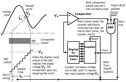
    The conversion from analog to digital form inherently involves comparator action whereby the value of the analog voltage at some point in time is compared with some standard. By applying the analog voltage to one terminal of a comparator and trigger a binary  which drives a digital-to-analog converter (DAC), the value of the analog voltage at some point can get. The output of the DAC is applied to the other terminal of the comparator. Since the output of the DAC is increasing with the counter, it triggered the comparator at some point when its voltage exceeds the analog input. The transition of the comparator stops the binary counter which is at that point holds the digital value corresponding to the analog voltage.

2) Successive Approximation ADC
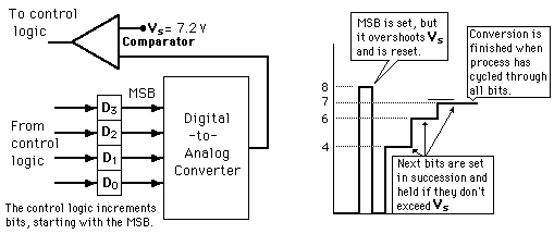
   This type of ADC is much faster than the digital ramp ADC because it uses digital logic to converge on the value closest to the input voltage. A comparator and a digital-to-analog converter (DAC) are used in the process. These is an illustration of 4-bit SAC with 1 volt step size.

3) Flash ADC
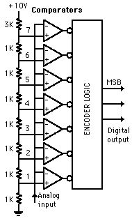
    A 3-bit flash ADC with resolution 1 volt is illustrated. The resistor net and comparators provide an input to the combinational logic circuit. Therefore, the conversion time is just the propagation delay through the network. Itis not limited by the clock rate or some convergence sequence. This type of ADC requires a comparator for each value of output although it is the fastest type of ADC. The ADCs are available in IC form up to 8-bit and 10-bit flash ADCs. A truth table has been executed from the encoder logic and then it is converted to the ladder of inputs to the binary number output.

Conclusion:
This week I am going to tell about the analog-to-digital converter (ADC) which is one of the important components to implement this project. This week I learned the type of ADC in industries and how this ADC will help me to do this project. 

Friday, 2 October 2015

FINAL YEAR PROJECT 1 (WEEK 4): Global Positioning System (GPS)

Objectives:

1) To study about Global Positioning System (GPS)
2) To know how GPS works

Methods:

1) By making research in the internet

Results:
How does GPS works
     Global Positioning System is a network of orbiting satellites that send precise details of their position in space back to earth. GPS is well-known for its military uses and was first developed by the US for the war. during early 1980s, the GPS is free to everyone with GPS receiver. Wherever you are on the planet, at least four GPS satellites are 'visible' at any time. Each one transmits information about its position and the current time at regular intervals. The signals is travelling at the speed of light intercepted by your GPS receiver which calculates how far away each satellite is based on how long it took for the messages to arrive. Your GPS receiver can pinpoint your location using a process called trilateration. It happens once it has information on how far away at least three satellites are. Imagine you are standing somewhere on Earth with three satellites in the sky above you. If you know how far away you are from the satellite A, then you will know that you must be located somewhere on the red circle. You can work out your location by seeing where the three circles intersect if you do the same for satellites B and C. Although it uses overlapping spheres rather than circles, it is just what your GPS receiver does. These satellites can be used to calculate a 2-D position which is latitude and longitude besides the track movement. The more satellites there are above the horizon, the more accurately your GPS unit can determine where you are. The receiver can determine the user's 3-D position which is latitude, longitude and altitude with four or more satellites in view. Once the user's position has been determined, the GPS unit can calculate other information such as speed, bearing, track, trip distance, distance to destination, sunrise and sunset time and many more. Nowadays, portable navigation device can give drivers their precise location to within a few meters and it is enough to navigate roadways. The 24 satellites that make up the GPS space segment are orbiting the earth about 12,000 miles above us. GPS is powered by solar energy but they also have backup batteries onboard to keep them running in the event of a solar eclipse when there is no solar power. Small rocket boosters on each satellite keep them flying in the correct path.
Three satellites that can give signals to GPS receiver 

Conclusion:
      This week I am going to tell about the Global Positioning System (GPS) which is one of the part that is very useful for this project as it is can located the place of the accident happens. This will save many lives as the ambulance and the family members who came to rescue the motorcyclist who involved in the accident become more faster compared than before. Before this, when the accident happens, the people who saw the accident will contact the ambulance and family members so that they will come to the accident's place but it is also a late response as they need to search the place of the accident. By using the GPS, the time to rescue people will become much shorter as it can give the accurate information about the accident's place.